I’ve always wanted an arcade machine for my home, its kind of one of those ultimate man-cave items that just completes a room. I also love Steampunk (seeing as my new EP is called Steampunk Cybercrunk, this should come as no great surprise). One drunken night I wondered whether I could combine the two. I find that the best way to get a project done is by setting a deadline, so I gave myself a few weeks (until my birthday as it happens). Also to keep costs under control, I set myself a budget of £300, which is about what you’d pay for a next gen console at the moment.
I found the whole experience immensely fun and rewarding. It wasn’t even that difficult, I had a few hairy moments, but I probably haven’t done any woodwork in 10 years. It took me about 3 weeks, working in little bursts over evenings and weekends but it was totally worth it. If you’re a gamer at heart and fancy a fun project (and earning some major real life EXP), I’d highly recommend it.
Buying the bureau
Rather than build my own arcade cabinet, I decided to modify a bureau. There are several reasons for this. Firstly, it fits the steampunk aesthetic extremely well. Secondly it takes up less space when not in use. Thirdly, as it remains hidden meaning amazed onlookers never see it coming. Lastly, the number of tools/workspace required is significantly lower.
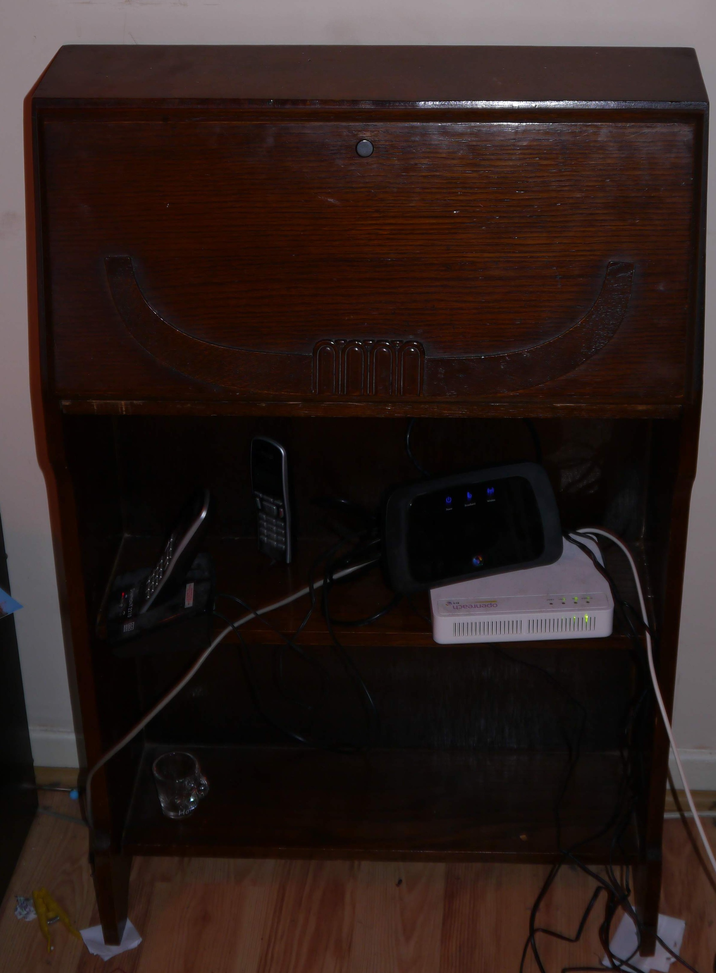
I got this one off eBay for £ 50 and there were a few available at around this price range. There are a few things to bear in mind when looking for a bureau to modify. Check its look (obviously), size (I needed a smallish one for the available space), internal design, and also what reinforcement the folding table has when extended.
There are several methods that manufacturers use for this. In this case all that attached the table to the cabinet are two small hinges and two sliding metal arms. This definitely needed some extra support. I figured its probably worth overengineering this a bit as having a large joystick unit mounted to it is not exactly what this bureau was designed for. As an added bonus, the extra added bits will just add to the the steampunk look.
Also make sure you check for stability and general quality to the unit. It’s going to need to be able to take the strain of modification and the forces of two people hammering buttons/waggling the joysticks chaotically
Fortifying the structure
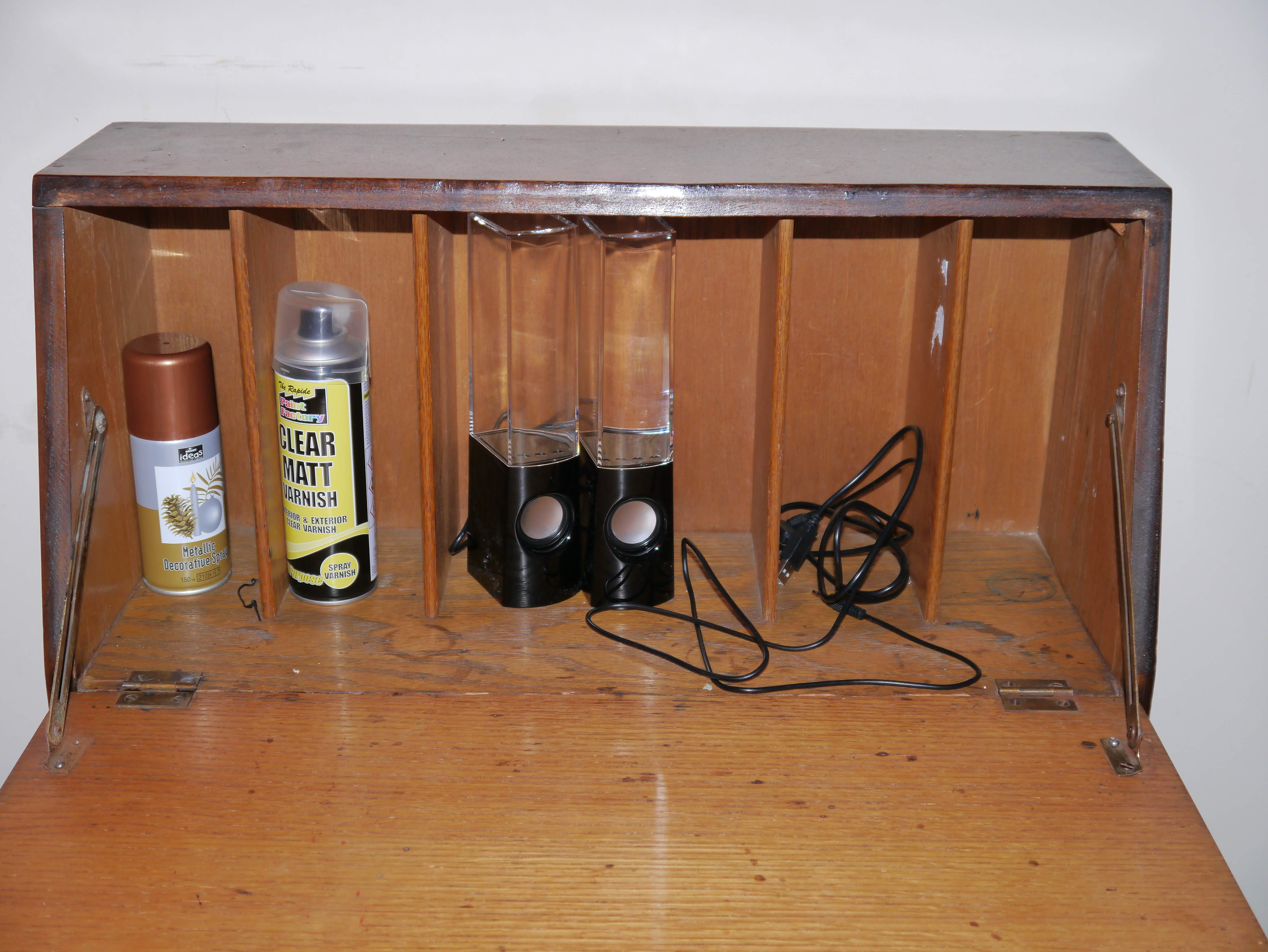
Firstly I removed the wooden dividers from the inside of the bureau to allow space for all of the parts. There was a little damage around one of the hinges which I glued with Gorilla glue. I also added a long continuous (Piano) hinge between the two existing ones to fortify it. These hinges will support the whole weight of the joystick unit when closed so it’s important to make them sturdy. As this cabinet did not have any support underneath the desk (many have some extending planks of wood for this) I cut out some supports from scrap wood and bolted these to the underside of the arcade shelf.
The thick bolt doubles as a rotating bearing. Some foam tape on top of these arms supports the weight of the desk without putting upwards shearing forces on the hinges. I also glued some lengths of wood to strengthen the join between the arcade shelf and the side of the bureau. The pre-existing sliding metal arms supporting the desk area feels pretty sturdy but only join to the desk proximally. As this table is going to potentially apply a fair amount of leverage to the hinges, I added a pair of chains connecting to pad eyes towards the back of the desk.

These help add support to the extended table. Finally I drilled some holes in the back panel using a hole saw. These provide spaces for the wires and ventilation
Building the control panel
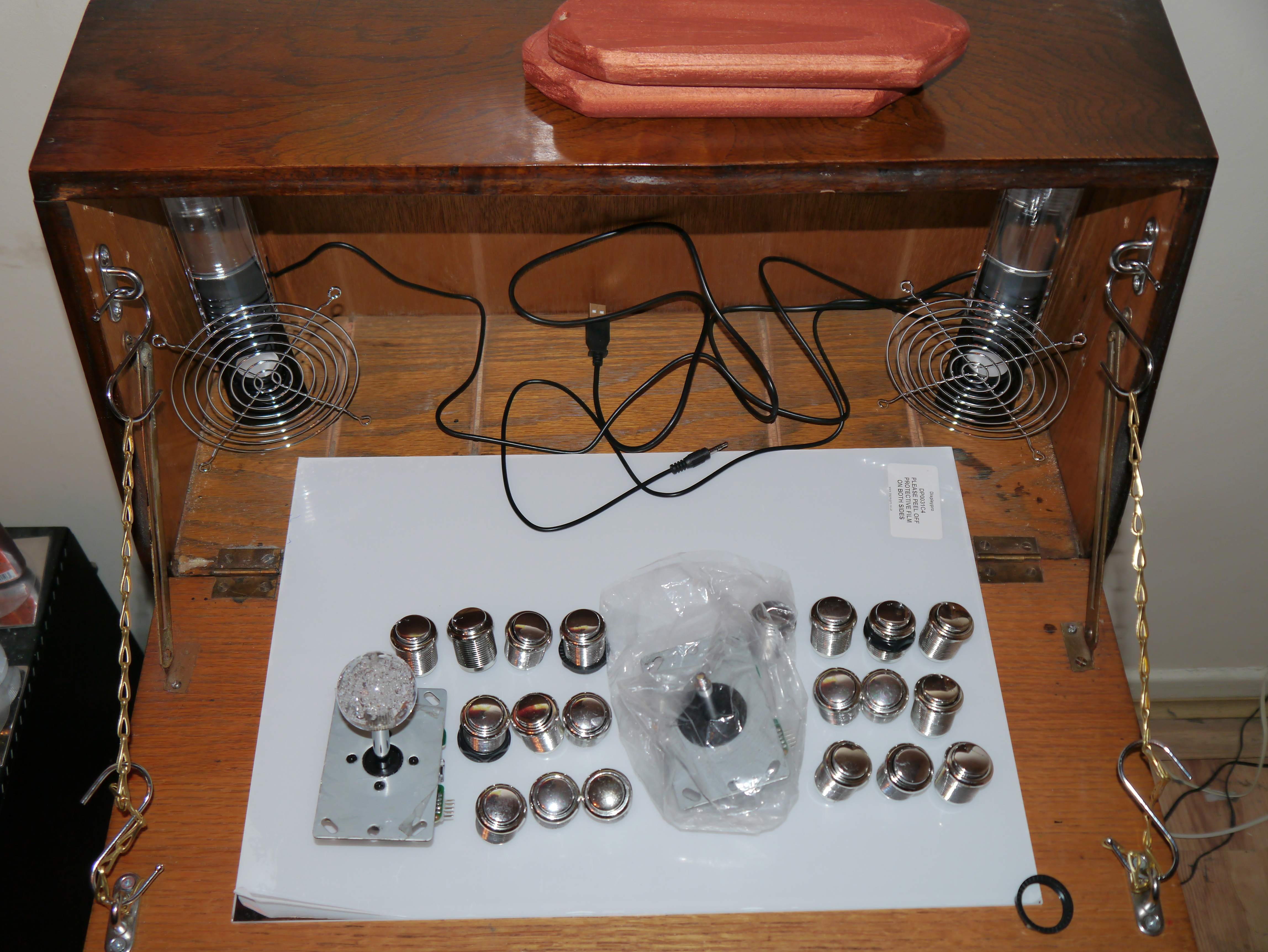
Ultimately the design I used for the joystick unit was pretty simple. A rectangular wooden frame supporting a piece of mirrored Perspex on which I’d mount the controls. I’d say planning is pretty vital at this stage to make sure everything fits together. The width of the control panel was limited by the width of the table I was mounting and the length of the piece of Perspex I had. Fortunately these two measurements were pretty similar. Accounting for the width of the frame there was just enough room for the joysticks and six buttons.
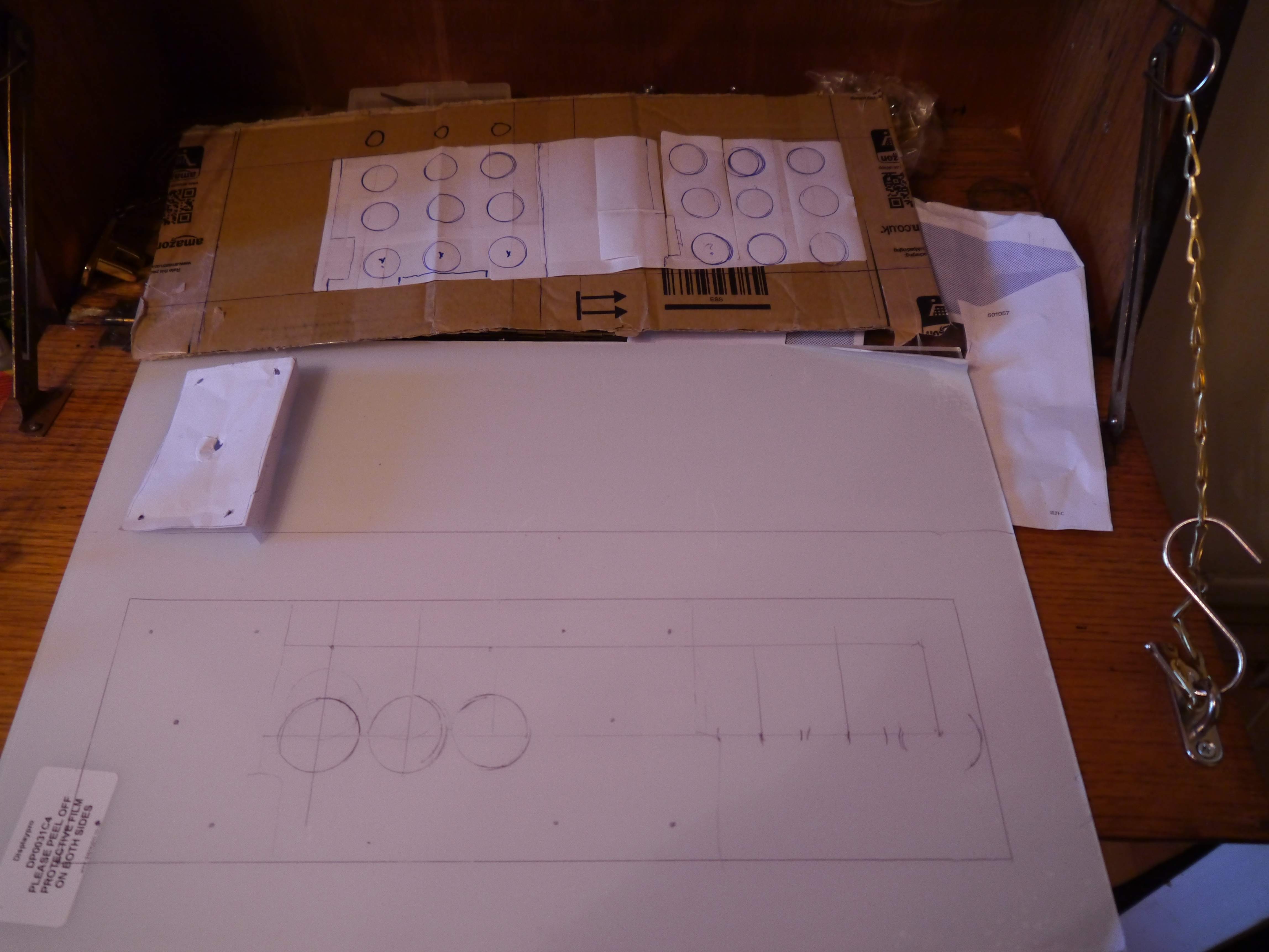
I’d really recommend making a cardboard/paper template to make sure that everything fits together before getting the saw out.
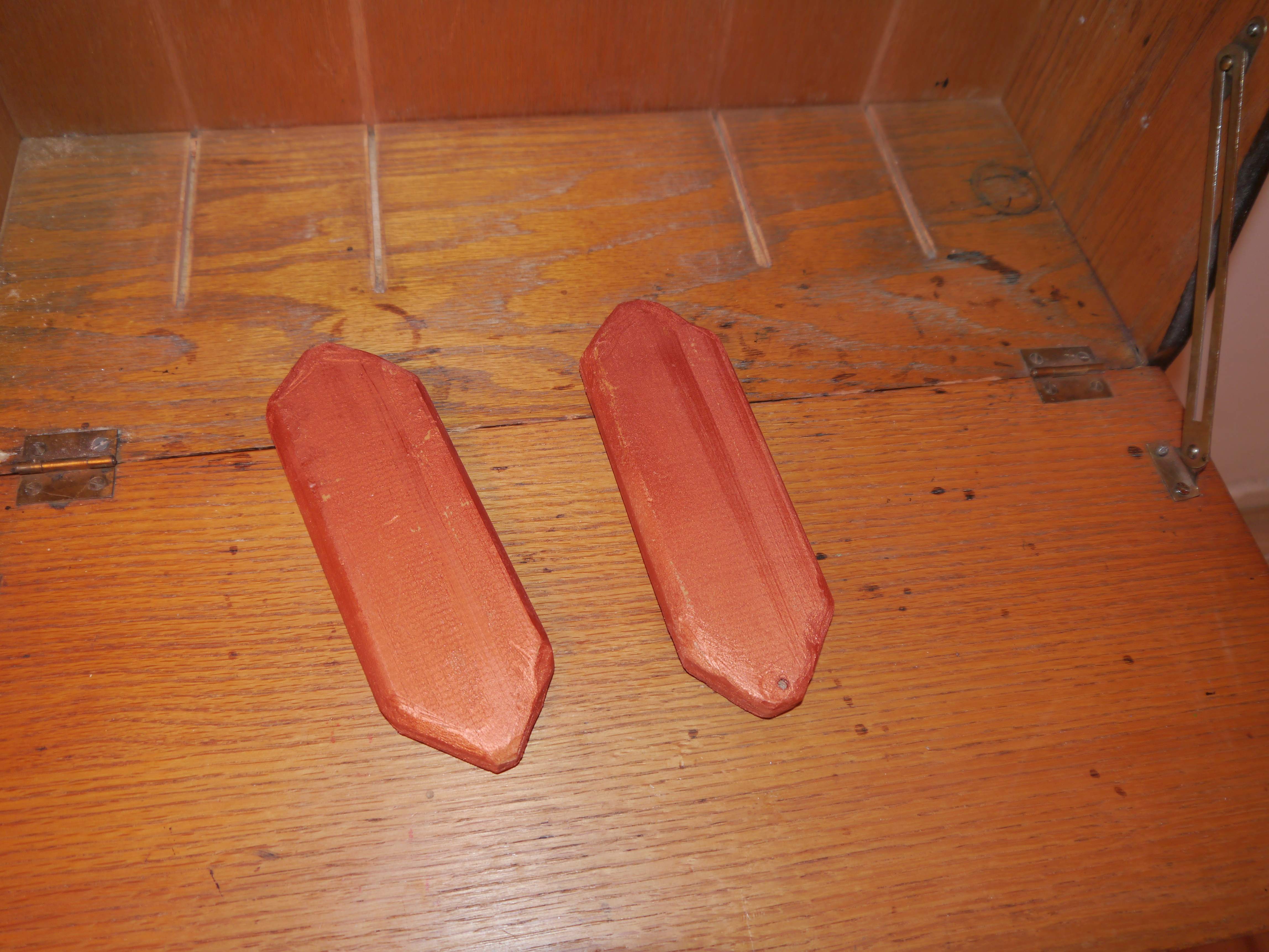
I started by making the frame. I decided to relent and actually buy the wood for this (rather than recycling) as I wanted to make it tall enough to accommodate the joystick mechanism (which was ~4 cm deep) and narrow enough to fit all the buttons etc. It’s definitely also worth checking the height of the joystick unit as well before starting to make sure it will fold nicely into the bureau and still leave enough room for the screen at the back. Once I was happy with all the dimensions I cut four lengths of wood and sawed lap joints at each corner. If you have a router or some other fancy tool, you could make a nicer joint than this but I don’t so I didn’t. I also drilled some holes in the back side of this for 4 extra buttons (P1/P2 Start/Select) and the wires. I glued the pieces together and sanded this down once so that it laid flat.
To smooth over any imperfections I then added a layer of foam tape to the bottom of the control panel. Finally like most of the added wood, I sprayed the frame in metallic copper paint.
Next I moved on to the piece of Perspex. It’s worth doing a final plan on the plastic film that wraps the Perspex sheet (as you can see above with my cardboard one). First I cut it down to size. Well I say cut. I tried to use the score and snap approach which reputably works quite well with Perspex. Despite what I’d read, this does not work as well as you might expect with a glass scorer so I got left with quite a bit of an uneven edge. It didn’t matter too much though as I’d planned to put the cut edge at the back anyway. I’d read online that trying to use a spade bit will just snap the Perspex so I drilled all the holes for buttons/joysticks with a hole saw. I did get a couple of chips and superficial cracking even using this approach. The best advice I can give is to make sure the Perspex is supported underneath and to drill a bit at a time, letting the drill cool off every few seconds. Or use a nice piece of hardwood ply instead of perspex. Finally I needed to drill some normal holes (i.e. drill bit) to bolt the joysticks to the control panel and attach the control panel to the frame.
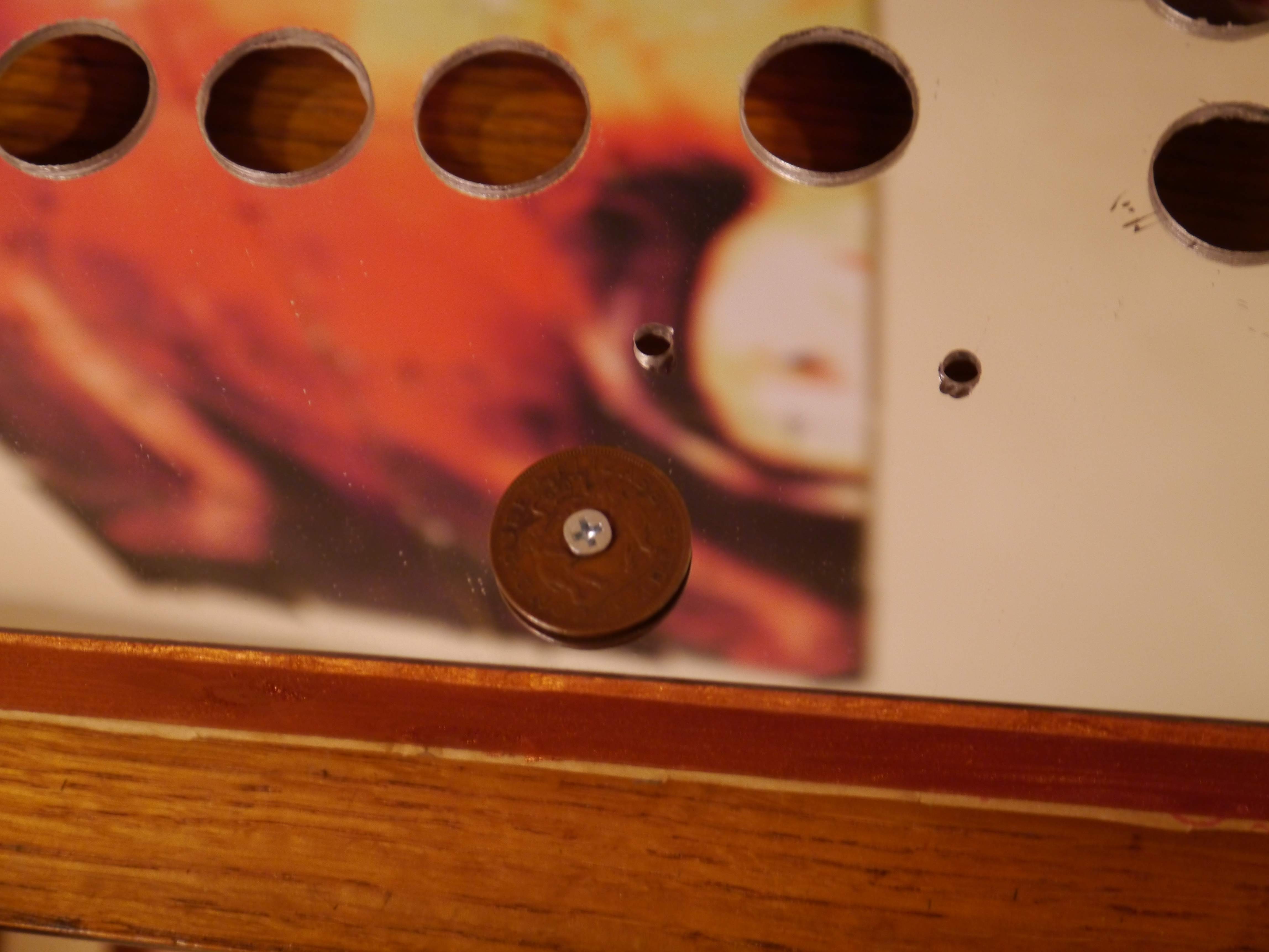
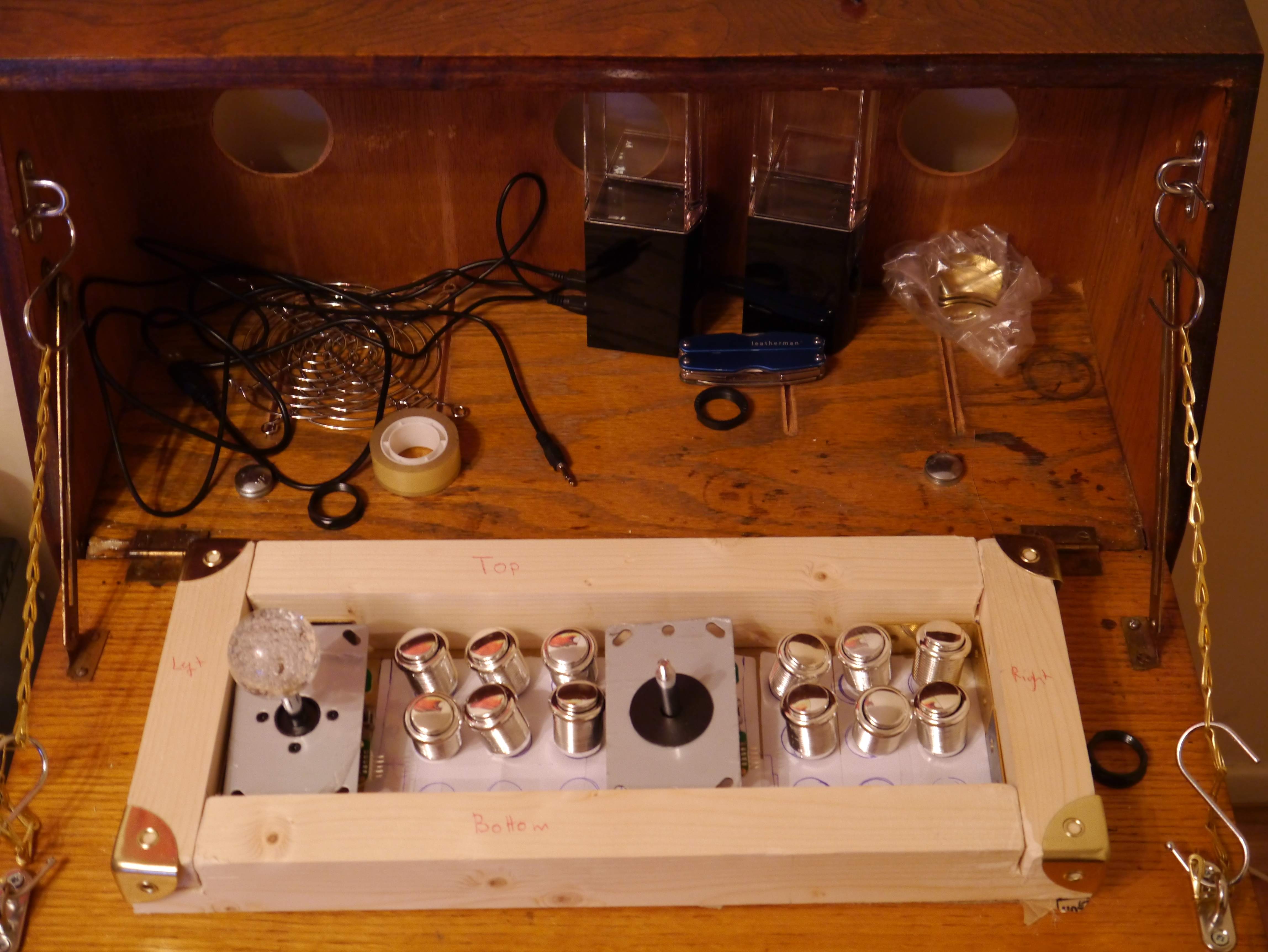
I then screwed the Perspex to the wooden frame using some brass corners for the front corners. For the rest of the screws I used some coins with holes instead of washers. I found some Rhodesian pennies in my coin collection but I would imagine Danish Krona would be just as effective (although wouldn’t have Queen Elizabeth II with a couple of elephants on them). Then it was just a matter of turning this control panel shell into an actual controller
Wiring the control board
This was one of the bits I was dreading but it actually was very simple. Firstly sand off the edges of the Perspex (on the outside and around all of the holes). Attach the joystick and buttons. The buttons in the back required a bit of Macguyvering to stay in place. I used some card/garden wire to use as a wedge. With these squeezed round the side of the button, I doubt they are going anywhere anytime soon.
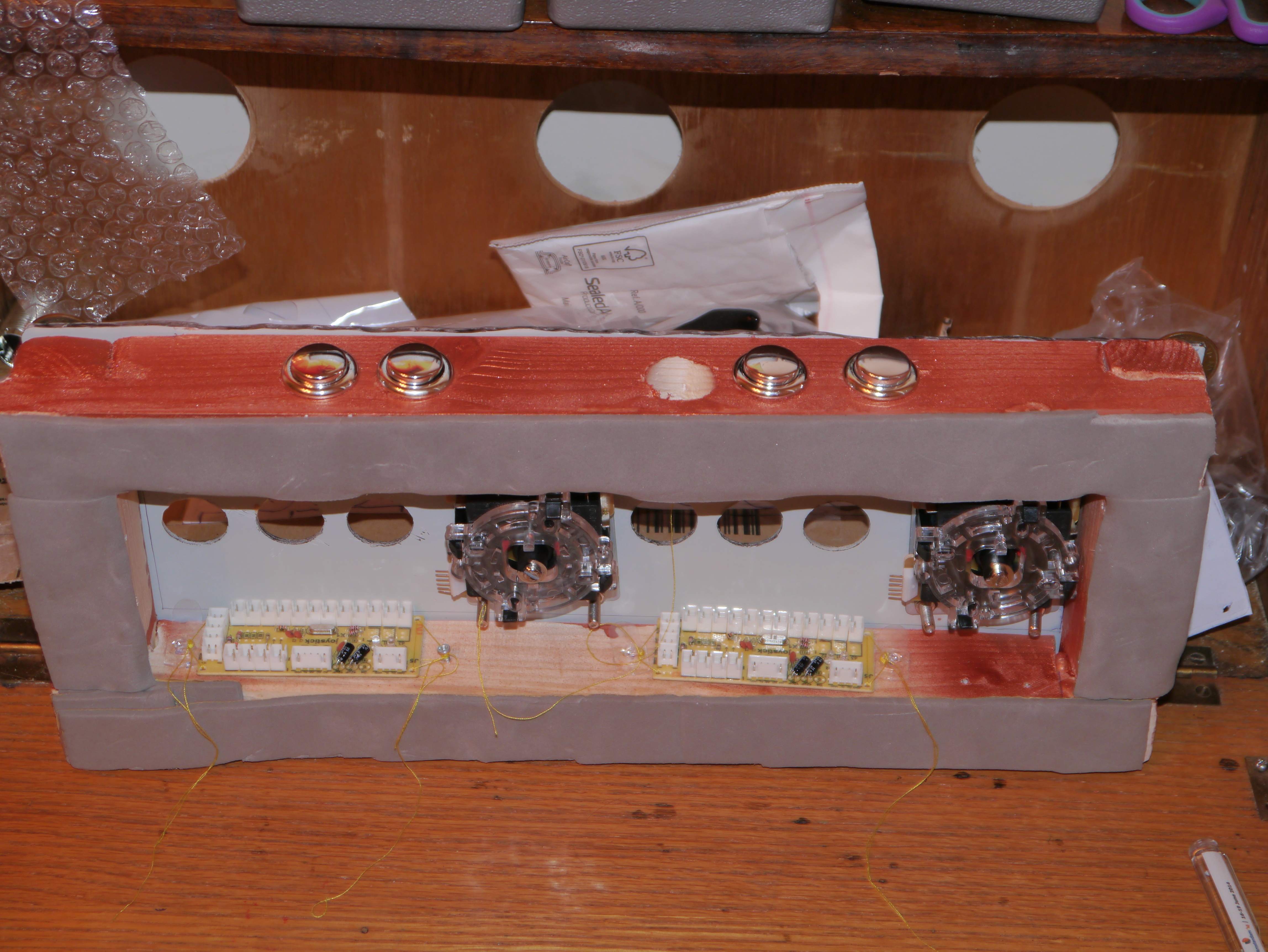
With all the buttons and the joysticks in place, its actually quite easy to fit the wires. The ZD board kit I got came with the metal disconnects already attached to the wires. It really is just a matter of slotting these onto the clips on the bottom of the buttons. Also this is a paired wire board so I didn’t need to daisy chain a common ground between all of the negative terminals.
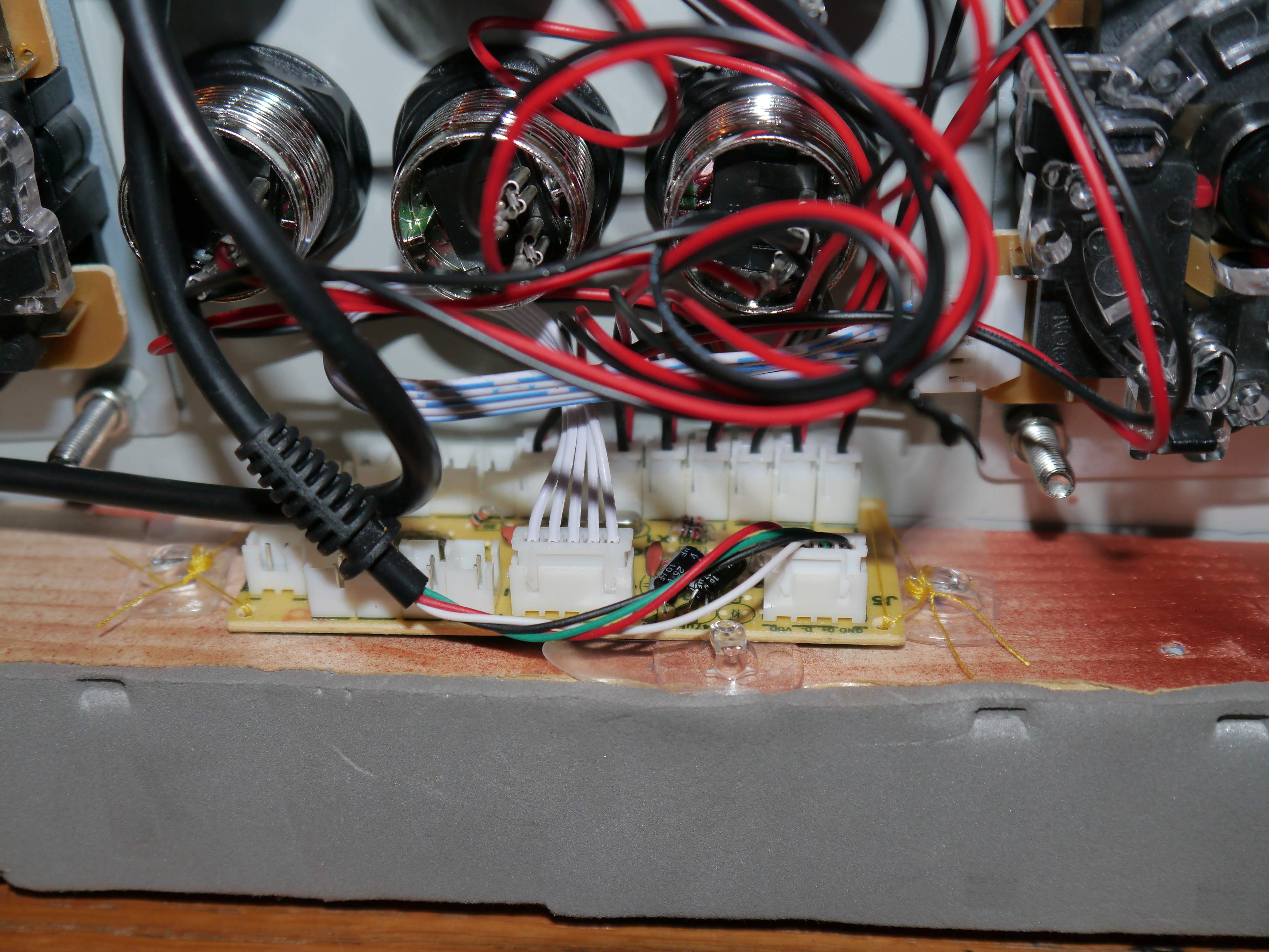
Using a 5 pin joystick also makes life a lot easier than an 8 pin one as it is only 1 ribbon cable to connect this rather than 8 wires. There are several good tutorials online on how to do the wiring, so if you’re following along at home and used different equipment to me, take a look around, it is highly probably someone has done it before (and been kind enough to take pictures)
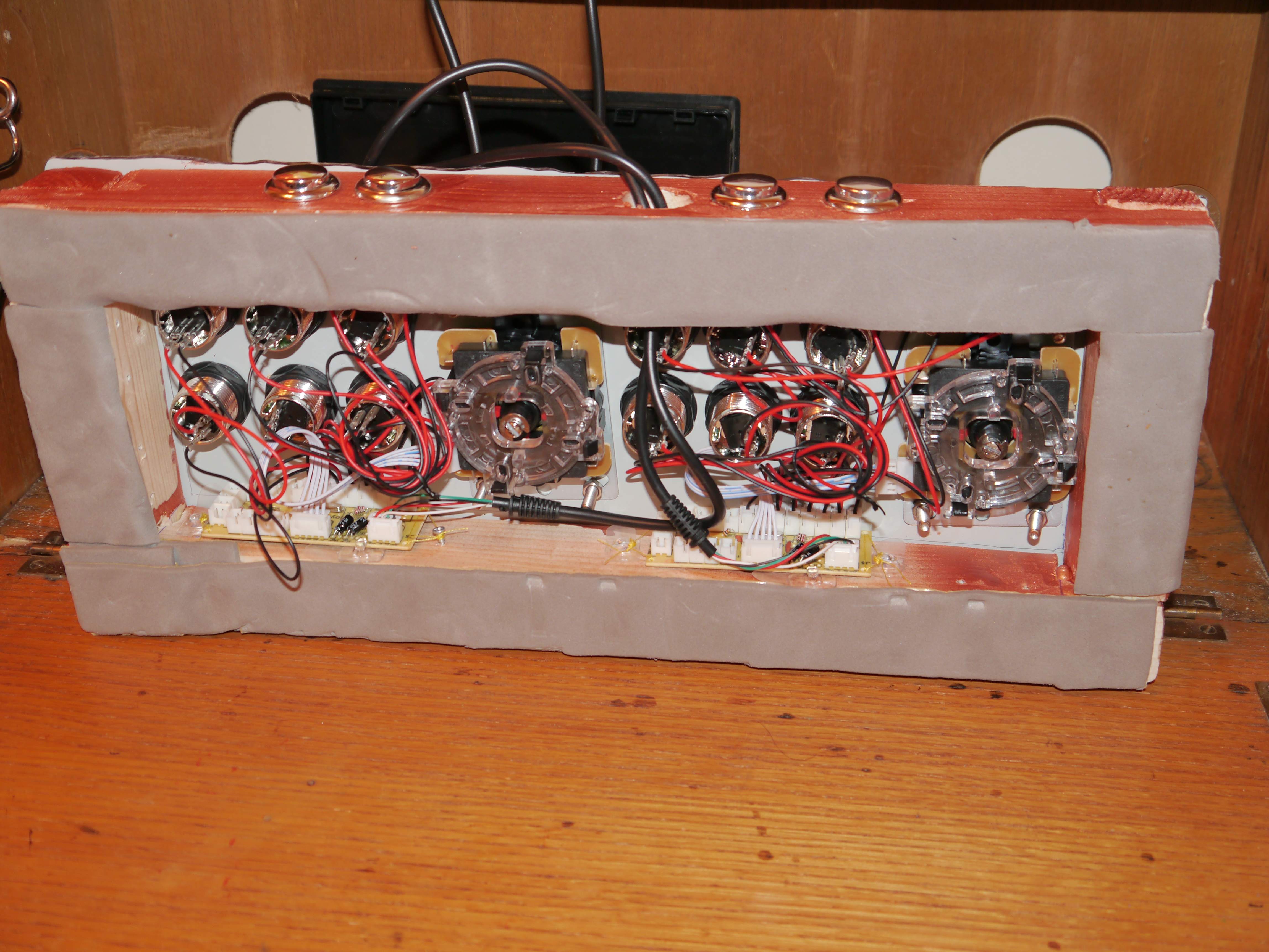
Finally I taped a piece of cardboard over the bottom of my control panel. This is mainly to stop the wires getting caught when its attached to the bureau. On which subject, attachment couldn’t be easier. I just used a couple of screw type sash window catches and attached it to the desk. Make sure you test that the desk will still close with the joystick in position before screwing the catches in place.
Of course at this stage you have a fully working 2 player arcade joystick that you could plug into a PC (or console/tablet etc) and just get going with the gaming. I’d actually advise doing this as a test at this stage, just to make sure everything is wired up correctly
Choosing a heart
Obviously for this to become an arcade machine, it would need some electronics inside to actually run the games. There were 2 main options for doing this: a computer or a tablet. There are obviously many options within these 2 categories but in the end I decided for this build it would be best to go with a tablet as they are cheaper (than a computer and screen), smaller and have a built in input system. If you are going down the tablet route, it is vitally important to get one that has an OTG (or full size) USB port and a separate DC port. A lot of tablets use one port for charging and attaching peripherals, which in this case would definitely not be desirable (as you couldn’t power it while the joysticks were attached). Using a PC would circumvent these issues and make set up easier in general. There is also a longer history of emulation on PC and better support but this would require a separate screen and more cabling. Using a Windows 8 (I’m shuddering at the thought of actually recommending win8) tablet might be a good compromise but they are currently a bit more expensive. One final option would be to use a development board (Raspberry Pi or similar) that has built in input pins meaning you wouldn’t need to use a seperate arcarde encoder. The only problem is its relative lack of processing power, but it does have a good selection of specially optimised emulators.
Apart from the seperate power and USB ports there are a couple of other considerations for choosing a tablet. I’d recommend a screen with a wide viewing angle and obviously enough processor power to actually run emulation. In the end I went for the fusion5 sharp4 which seems to be functioning more than adequately for the purpose. Also they are relatively cheap, have a UK based warranty, an IPS screen (for viewing angle) and solid feeling build quality.
Mounting the tablet
On one hand, you could just buy an off the shelf stand/case for this purpose, on the other making one out of vintage meccano is way more fun. It also really looks the part, but then again it should, as meccano is basically just Victorian engineering for children. I would advise putting some foam into the section where the tablet actually sits to stop any exposed bolts etc. scratching the screen (I also put a screen protector on just in case)

After I’d made the actual stand for the tablet, I made a surround out of recycled patterned cardboard to hide the majority of the wiring. Then a second surround made of meccano completes the tablet frame. I also put the speakers in place too with some mirror tiles around them (for reasons that I’ll explain a little bit further down).

I haven’t included the cost of the meccano as I had it lying around from my last steampunk project but there are loads of job lots on eBay (or you could always check that dusty box at the back of the attic)
Wiring the cabinet
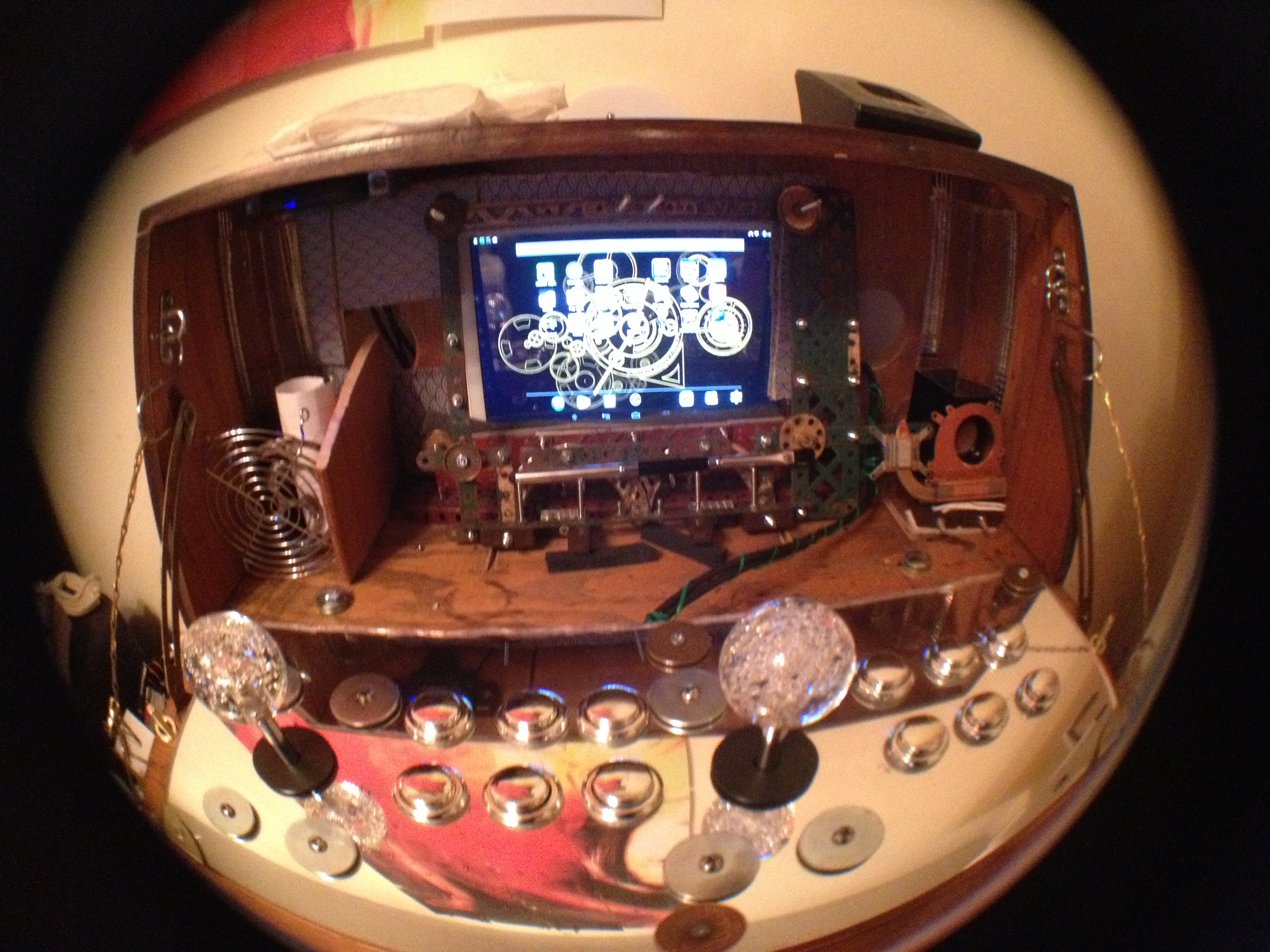
All of the holes I made before make this surprisingly easy to wire up and keep said wires out of view. At the back, I attached a cheap (£1) laptop cooler over the central hole where the tablet is and a UFO LED above it to light up the wall (whoever heard of an arcade machine without lights).
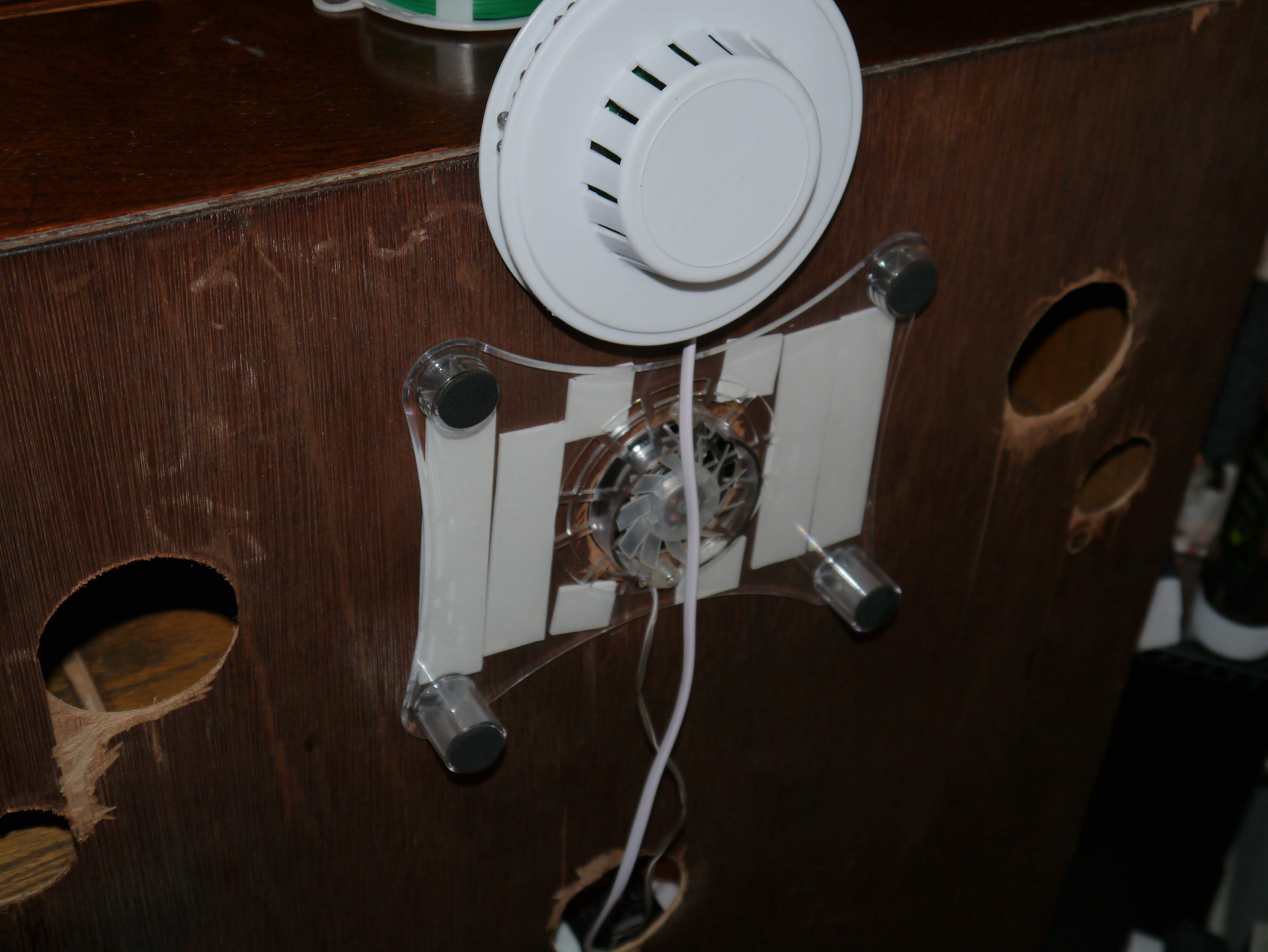
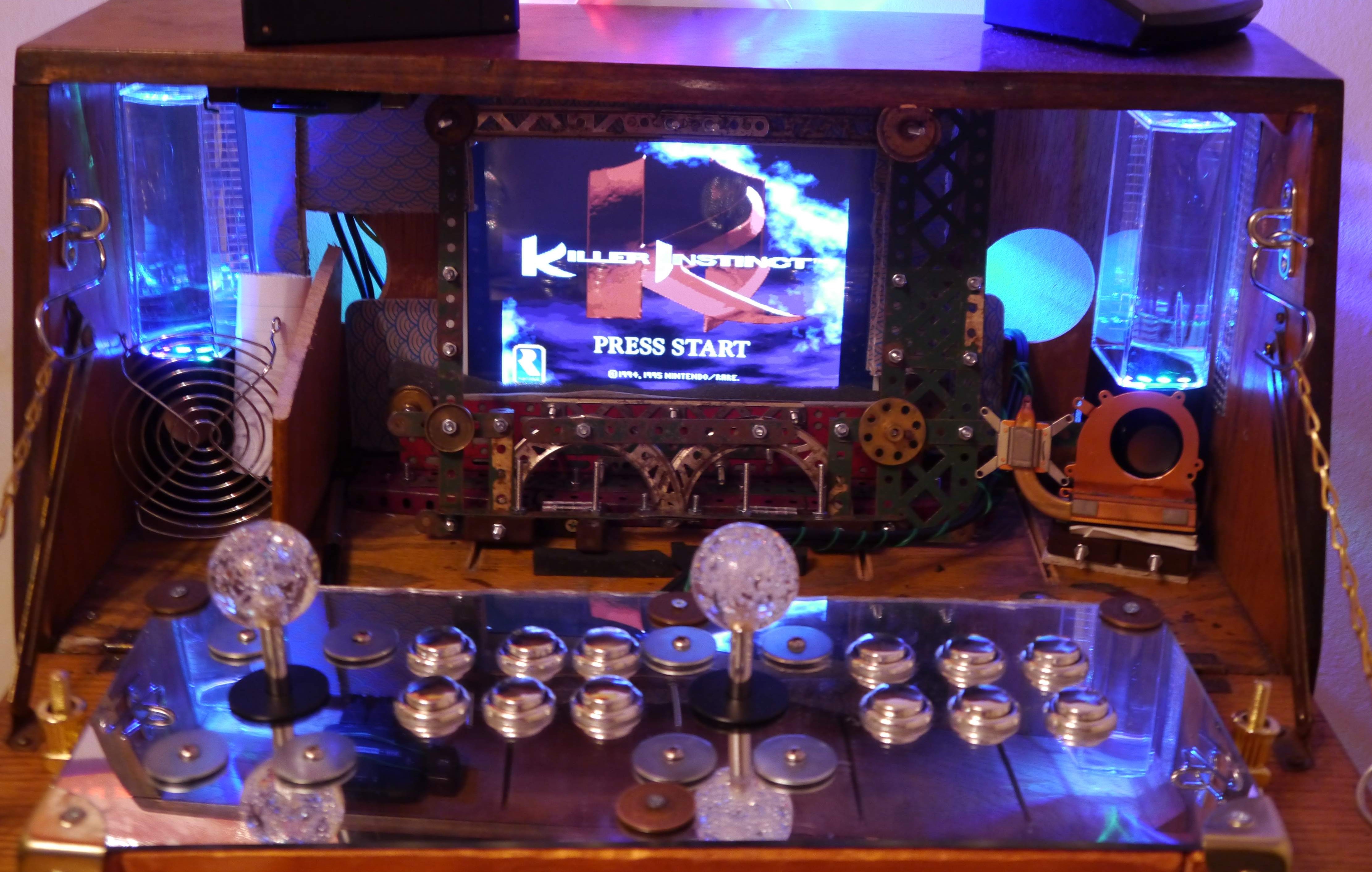
The tablet needed 3 connections: power, USB hub and sound. These are all bundled into 1 corner, which helps with clutter. I actually mounted the usb hub to the roof of the desk section. This is between 2 fixing blocks held up with garden wire, which creates a nice slide mechanism to access the additional USB port (2 of them are taken up by the joysticks). The speakers and the laptop fan both need 5V power, which is handily provided by a generic USB power adaptor. I mentioned earlier that these were special speakers, the large clear portion on top is actually a waterjet unit that fires tiny fountains of illuminated water in time with the audio. Apart from looking awesome, it also makes the lighting sound reactive, making for a more immersive arcade experience. The mirror tiles increase the amount of brightness that they put out. At this point the hardware is ‘finished’, at least for a first draft
Setting up the machine
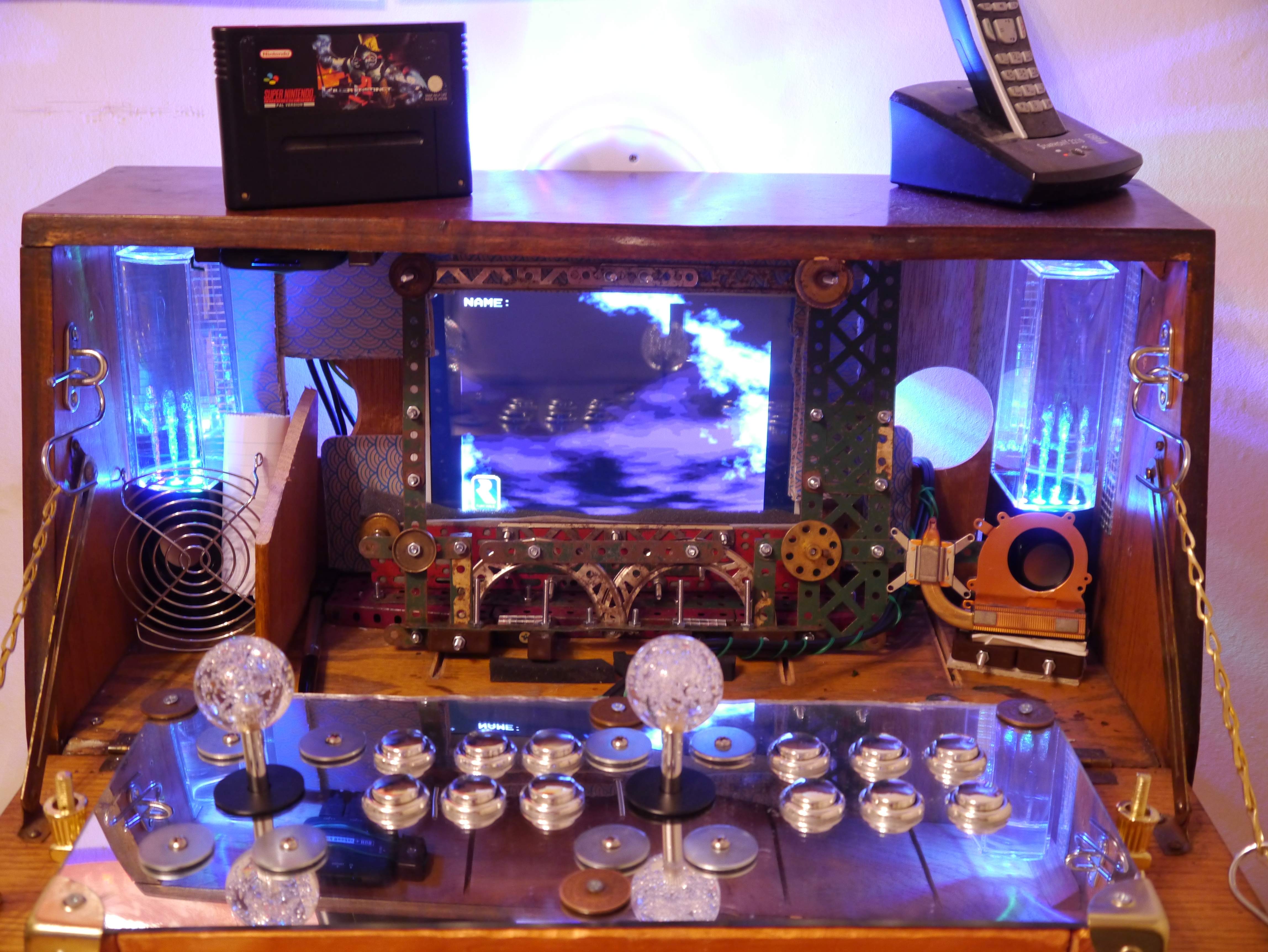
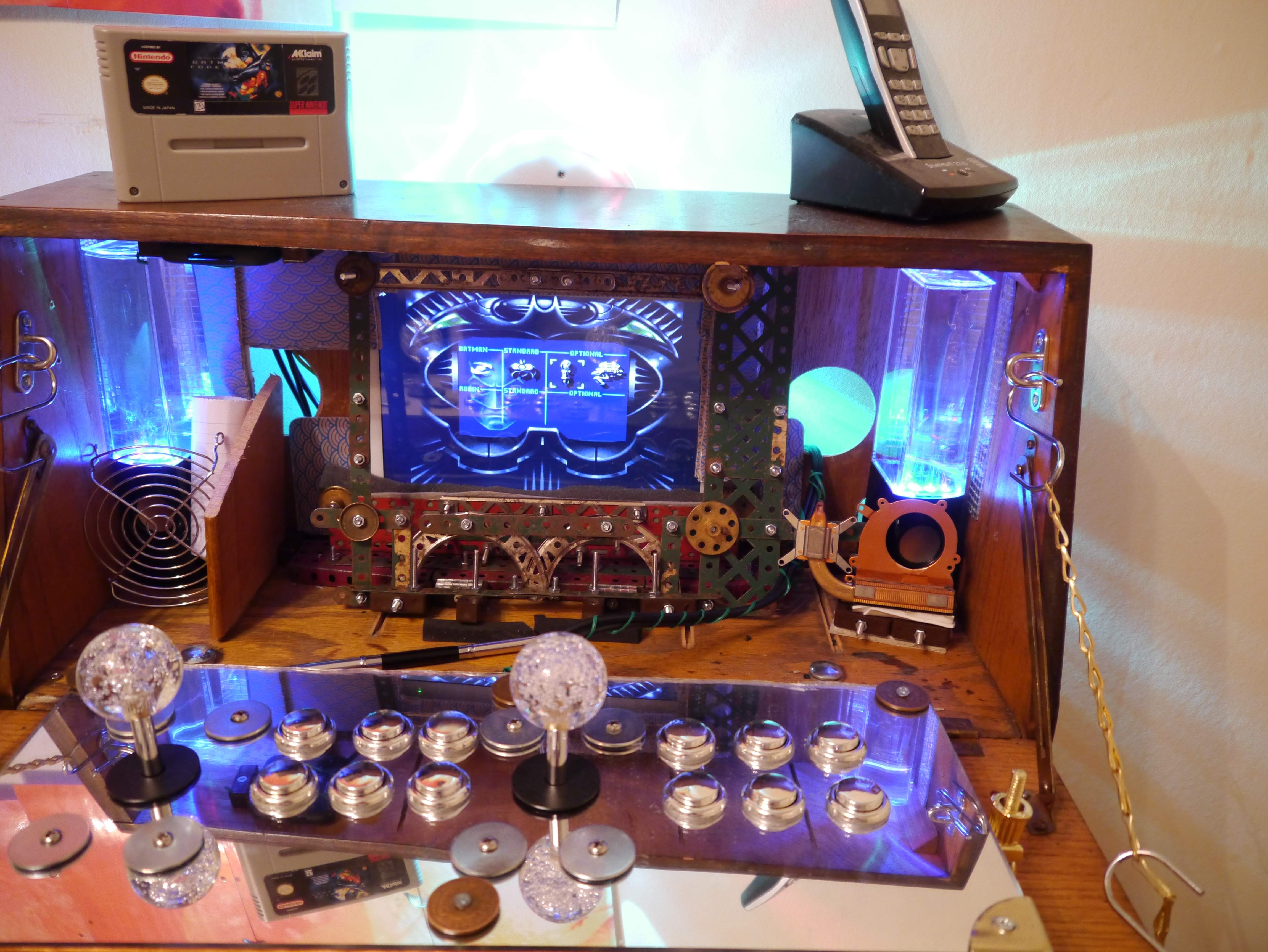
There are a couple of things you need to set up the emulation on the tablet. Namely emulators (pieces of software designed to replicate the function of pieces of hardware) and ROMs (the actual games to play). The distinctly murky legality around ROMs is kind of beyond the scope of this article and pretty much comes down to personal ethics anyway (as being prosecuted for downloading a 20 year old game you don’t own is pretty unlikely). Just to keep things nice and clean though, here is the machine running SNES emulation and the SNES cartridge (which I own) next to it. Nothing contentious going on here.
The Zero Delay boards I used in the joysticks are plug and play … for PC. Unfortunately Android (4.4) would not recognise them. All is not lost though as there is the rather helpful program called USB/BT joystick centre that lets you set up a custom driver for any unrecognised peripheral (which let me just say is an amazing principle). For some unknown reason it was happy setting up player one as a generic gamepad but required me to set up a custom driver for the second one. Even so 5 minutes later and everything was working like a charm. Ready player one …
Cost/materials
| Item | Source | Unit Cost (£) | Quantity | Total |
| Bureau | Ebay | 48 | 1 | 48 |
| Fusion5 Sharp4 tablet | link | 110.09 | 1 | 110.09 |
| Arcade encoder | link | 6.67 | 2 | 13.34 |
| Chrome buttons | link | 13.28 | 2 | 26.56 |
| 2xJoystick pack | link | 17.34 | 1 | 17.34 |
| Sash window fasteners | link | 2.5 | 4 | 10 |
| Chest corners (8) | link | 3.75 | 1 | 3.75 |
| 7 in 1 OTG hub | link | 4.89 | 1 | 4.89 |
| Acrylic mirror | link | 6.55 | 1 | 6.55 |
| Iboutique colourjets | link | 16 | 1 | 16 |
| Wood fixing blocks (50) | link | 3.6 | 1 | 3.6 |
| Stainless steel pad eyes | link | 1.74 | 4 | 6.96 |
| S hooks (8) | link | 1.89 | 1 | 1.89 |
| 1.5 m brass chandelier chain | link | 3.99 | 1 | 3.99 |
| copper spray | link | 3.99 | 1 | 3.99 |
| fan grill protectors (2) | link | 2.34 | 1 | 2.34 |
| Varnish spray | link | 4.21 | 1 | 4.21 |
| 30 cm piano hinge | link | 4.35 | 1 | 4.35 |
| Softwood Timber 34x44mmx1800mm | link | 3.22 | 1 | 3.22 |
| Nuts and bolts pick and mix | Wilkinson | 3 | 1 | 3 |
| Recycled wood | From old bed frame | 0 | 1 | 0 |
| Vintage meccano | Left over from previous project but originally cost £10 from ebay for the job lot | 0 | 1 | 0 |
| Assorted screws, nuts and other hardware | lying around | 0 | 1 | 0 |
| Foam | Recycled from packaging etc | 0 | 1 | 0 |
| Grand total | £ | 294.07 |
Well that’s about it for now. I had a lot of fun doing this, and its a project that’s well worth the time put in. I’ll add some more pics soon as well as a list of my favourite retro steampunk games to play on.
Dataphiles – Steampunk Cybercrunk EP is out Q1 2015, and there’s lots to do in the meantime 😉
Love and Peace,
D
